
Disassembly of the Portable Electronic Ballot and iVotronic machine is a fairly straight-forward procedure. To get the outer casings off of both the PEB and the machine requires a security torx screwdriver or bit; however, the internal screws require only a standard Phillips bit.
Once the screw on the back of the PEB is loosened, additional force might be required to unseat the plastic pins that keep the casing and motherboard in alignment. Care must be taken, however, as these pins can easily break and possibly damage the board.
Once the PEB is opened, the motherboard simply slides of the pins and is not in anyway secured to the casing. One side of the board is populated with a plethora of electrical components, from large integrated circuits and oscillators to minuscule resistors and capacitors no larger than a grain of rice. The other side of the motherboard only contains the battery that powers the hand-held device, a regulating capacitor, and an array of pins that will be used to interact with the board's microcontroller.
Interaction with the microcontroller requires a PICKit device from the chip manufacturer, Microchip Inc. This project used a PICKit 3, however, the older ES&S hardware may be more appropriate for a PICKit 2. Unfortunately, the pins on the PEB to not match up one-to-one with the pins on the PICKit 3, however the image below shows the configuration that was capable of reliably transferring information between the two devices. See Hacking the PEB for more in-depth information.
The plastic casing is secured with nine secure torx screws, and a long, thin bit is required to get as some of the deeper-seated ones. Removal of the plastic casing reveals the large motherboard and the numerous modules seated onto the board and cables that combine the disparate components into one functional machine. The board screws directly into the metal plate that separates it from the touchscreen interface in at least 6 locations, and various cables will also need to be detached to fully separate the circuitry for a closer look. Photographs at this point will ensure that cables are properly reattached when the machine is reassembled.
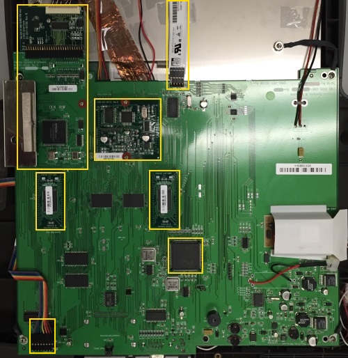
The along with the components soldered onto the motherboard, there are also four modules seated onto the board. The sound module and the video driver are secured to the motherboard using two screws each in addition to the pins that connect them to the rest of the circuitry. Care must be taken when removing these to not bend the header pins during removal; having said that, substantial force may be required to overcome the collective friction of 40+ pins.
In addition to the primary board, there are various smaller component boards that attach via cables that include PEB-communication circuitry and provide a seat for some of the buttons on the front of the machine. All of these components are secured with only a single screw.